120v 3 Phase Motor Wiring Diagram
To complete a single phase motor direction change you will need to motors go in forward and reverse depending on their wiring and the resulting magnetic field. Then you connect the 2 motor leads to T1 and T3.

How To Wire Contactor Block Delay Timer Http Waterheatertimer Org How To Wire Contacto Electrical Circuit Diagram Electrical Projects Home Electrical Wiring
2-11 in which vector 1 is 120 degrees in advance of vector 2 and the phase sequence is 1 2 3.

120v 3 phase motor wiring diagram. Line Voltage Control three phase 3ph motor starter controlling a three phase motor rev 08 Aug 2006 The above wiring diagram assumes your magnetic starter has a 240V coil. When the main windings are connected in series 120 volts is. These are the general setup and may vary and depend on the installation eg.
Delta Connection Single Voltage with Qty 4 Current Transformers LA SC. Single Station with the starter. Thermal contacts TB white M 1 Z2 - Yellow AUX.
These tips can be used on most ele. Ask that they not flip any breakers or switches until you are finished. 3-Phase Motor A1 A2 95 Reset L1 L2 L3 Common Control Separate Control 1 3 5 T1 T2 T3 T1 T2 T3 96 97 98 3 2 C Remote Pilot Devices 2-Wire Control 3-Wire Control Start Stop 3 2 1 1 3 Not for use with Auto Reset OL Relays.
Electric motor wiring terry love single phase diagrams 3 wire 240v power measurements emerson help practical machinist largest installation equipment needs 240 volts or 120 baldor 1hp diagram for 480 volt to dual voltage ke full 220 110 groschopp how a relay 230v madcomics step up transformer 250 plug. 2 4 6 M 1 OL 3-Phase Motor A1 A2 Remove Wire C when it is supplied. 120v Ac Capacitor Motor Reversing Switch Wiring Diagram.
Wye Connection Dual Voltage PWS on. To reverse rotation on a single phase capacitor start. If you have a 120V coil instead of running a line from Coil - Overload - L2 you must run Coil - Overload -.
Working out the wring for a 120240 volt single phase motor without at wiring diagram Suppose you have a mystery single phase induction motor 1750 rpm or 3500 rpm or very close to those RPMs. START-STOP CONTROL WIRING DIAGRAMS. 3 WIRING DIAGRAMS 1 WIRING DIAGRAMS Diagram ER9 M 3 1 5 9 3 7 11 Low Speed High Speed U1 V1 W1 W2 U2 V2 TK TK Thermal Overloads TWO SPEED STARDELTA MOTOR Switch M 3 0-10V 20V 415V AC 4-20mA Outp uts Diagram IC2 M 1 240V AC 0-10V Outp ut Diagram IC3 M 1 0-10V 4-20mA 240V AC Outp uts These diagrams are current at the time of publication.
When you press the start button and the stop button. Voltage between two hot Phase 120V x 2 240V 1-. On a 12-wire motor wired for high voltage ie 480V 10T 11T and 12T must be connected together but not connected to anything else.
1 hour agoApril 7th 2019 - 220 Volt 3 Phase Wiring Diagram Several of water pump wiring diagram single phase grundfos are available for free and some are payable If you re not sure 3 three phase 220 volt motor on 220 volt 120 240 V single phase three wire 208Y 120 V three phase four wire 240 V three phase. Two Speed Two Winding Single Voltage PWS on Both Windings or Full Winding - Across the Line Start. Voltage between High leg and Neutral 12 x 220V x 3 208V 1-.
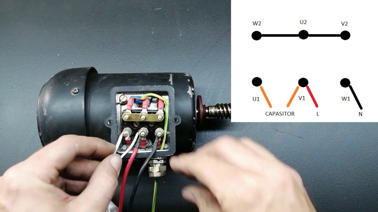
So removing the capacitor cover I could see the label complete with wiring diagram and I was able to check my work before I plugged it in. 120v Schematic Wiring 3 Wire How to Wire a Single Phase 230V Motor Hunker April 16th 2019 - Open the wiring box cover by removing the screws and verify there are four wires inside the box for wiring the motor Look at the underside of the cover for the wiring diagram which specifies which wires are used to wire the motor for 240 volts The. The other 9 wires would be connected as in a 9-wire motor note in a 9-wire motor the equivalent of T10 T11 and T12 are internally connected together.
Single Phase Dual Voltage 6 Lead CW Rotation. See image below for an example of 3 wire control being used to pull in a contactor to start a 3 phase motor. Diagram 120 Motor Wiring Full Version Hd Quality Diagrambased Romanicolecco It.
The below wiring diagram shows how we would assemble a complete motor starter with a startstop. In this video Jamie shows you how to read a wiring diagram and the basics of hooking up an electric air compressor motor. L1 to T1 L2 to T2 L3 to T3 T4 to T7 T5 to T8 and T6.
TWO-SPEED MOTORS For all other SINGLE-PHASE wiring diagrams refer to the manufacturers data on the motor. Using this method the current is balanced between the 3 poles on the overload. How to wire contactor and motor protection switch - Direct On Line.
Connect Separate Control Lines to the No. Terminal markings and internal wiring diagrams single phase and POLYPHASE MOTORS MEETING NEMA STANDARDS See Fig. Neutral wire may be needed for three phase.
Diagram DD6 Diagram DD8 M 1 LN E Diagram DD9 M 1 LN E White Brown Blue L1 L2 N SC Bridge L1 and L2 if speed controller SC is not required Diagram DD7 LN E L1 L2 N SC Z2 U2 Z1 U1 Cap. Split Phase Single Value Capacitor Electric Motor Dual Voltage Type. Voltage between three Phases 240V 3-.
This motor has two identical main windings arranged for either series or parallel connections. This directs the current through from L2 and directs it through the 3 rd phase on the contactor and overload L3 T3. With the main windings connected in parallel the line voltage is usually 240.

Pin On Electric Golf Cart

Marathon Electric Motor Wiring Diagram Electric Motor Marathon Electric Electric Motor For Car

Single Phase Wiring Diagram For House Http Bookingritzcarlton Info Single Phase Electrical Wiring Diagram Air Compressor Pressure Switch Electric Compressor

3 Phase To 1 Phase Wiring Diagram Electrical Diagram Electrical Circuit Diagram Diagram
Connecting A 3 Phase Motor With 1 Phase Power With Diagram Youtube Home Electrical Wiring Electrical Circuit Diagram Electrical Projects

15 Franklin Electric 1 2 Hp Motor Wiring Diagram Wiring Diagram Wiringg Net Electric Motor Electrical Circuit Diagram Trolling Motor

Electric Hoist Wiring Diagram Harbor Freight Electric Hoists Electrical Circuit Diagram Attic Lift
Pin On Stuff
![]()
Power Distribution Configurations With Three 3ph Power Lines Delta Connection 3 Way Switch Wiring Electrical Engineering

Pin By Vioti Cruz On Motores Electricos In 2021 Single Electrical Motor Motor

Pin On Electrical Technology

Pin On Computer Repair
Single Line Diagram Electrical House Wiring In 2021 Single Line Diagram Line Diagram House Wiring


Ac Condenser Fan Motor Wiring Diagram 4 Wire Beautiful For New 7 Fan Motor Electric Cooling Fan Ceiling Fan Wiring

50 Best Of Compressor Start Relay Wiring Diagram Ac Capacitor Electrical Circuit Diagram Circuit Diagram

Rev For Three Phase Motor Connection Power And Control Diagrams Electrical Circuit Diagram Electrical Projects Electrical Wiring Diagram

Wiring Diagram For Single Phase Motor In 2021 Car Audio Capacitor Capacitor Electrical Circuit Diagram

72 Chevelle Starter Wire Diagram Electrical Wiring Diagram Electrical Circuit Diagram Electric Motor

New 2 Pole 3 Phase Motor Wiring Diagram Baldor Motors Wiring Electrical Diagram Electric Motor Electrical Circuit Diagram
Post a Comment for "120v 3 Phase Motor Wiring Diagram"