100w Spectra To Tone Remote Wiring Diagram
Reconnect the battery ground cable. For speakers with wire attached but the same colored wires most have some small printing on the positive wire be sure to check closely.
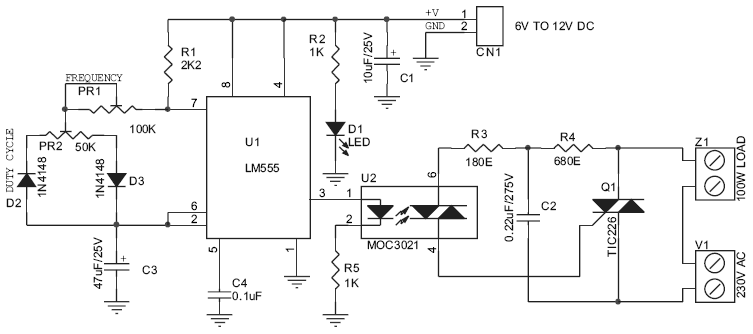
Diagram 12v Lamp Flasher Circuit Diagram Full Version Hd Quality Circuit Diagram Mediagrame Antichemurasorrento It
TK Math DeviceDongle Pinout.

100w spectra to tone remote wiring diagram. The Astro Spectra can be identified by a W3 W4 W5 W7 or W9 control head. RIB TO MSF5000. If you are using a Pelco Coaxitron controller leave SW in the default OFFPelco Spectra Iv Wiring Diagram Through the thousands of pictures online with regards to pelco spectra iv wiring diagram picks the top collections using ideal quality only for you.
GP60 Series GP68 HT600. Another option for providing a proper remote turn on circuit is to wire constant power and ground to a switch and then wire the output of the switch to the amplifiers remote turn on. Do keep remote receiver wiring away from noise sources.
This is usually done to trace the location of a cut or missing door window or other alarm wire. While 24GHz systems are impervious to noise that comes in through the antenna RF noise noise can still. PC TO C200 Tone Remote.
A tone and probe set can also be used to identify unlabelled wires that run to remote locations from a central alarm panel. If you are looking for the pinout of the HLN1196A Auxilliary Switch Panel then you will want to look here. C3446M-B 809 9 Description The Spectra Mini IP dome system is an indoor mini do me system with a built-in 100Base-TX network interface for live streaming to a standard Web browser Microsoft Internet Explorer or Firefox.
I just purchased a Spectra mobile that came with no installation instructions for the Motorola Spectra Radio T99DXW_Astro P25 VHF w Read through all of the pages to help identify exactly which diagram works. If you want to connect a MDC1200 unit to a Spectra you need this diagram. The tone remote adapter lets you control a mobile radio at a remote location from a desktop console using high-level guard-tone signalling commonly used with full-size base stations.
The Spectra Mini IP dome features open architecture connectivity for third-party software recording solutions. By routing your remote receiver wires away from noise sources like ignition batteries switches ESCs ECUs youll eliminate any chance of a form of interference called inductance. M1225 Service Manual 6880904Z96-A 137 MB PDF Donated by Eric Lemmon WB6FLY.
Spectras come in many frequency bandsplits called Ranges. Stereo Wiring Diagrams. Here Ive provided you with a speaker diagram showing basic connections I explained several important things you need to know about speakers and speaker wiring.
Connect ammeter lamp 60-0-60-I only to existing instrument panel lighting circuit. Wiring Diagram 4 Switch 120 V 5060 Hz 3. PC TO COMMAND PLUS.
See Wiring Diagrams 3 and 4. Below is a list of the available ranges for VHF and UHF. See Wiring Diagrams 1 and 2.
For links configured as HWQS Power Panel LT-1a link terminators must be installed across terminals 3 and 4 at both ends of the daisy chain link when the total wiring exceeds 50 feet. WIRING REMOTE TURN ON TO A SWITCH. Do not pinch the wires.
If ammeter shows a positive charge when starter is engaged reverse connections on back of ammeter. The problem with wiring the. A tone and probe kit is used to trace wires or cables by sending a signal from one end of a wire along its entire length.
Diagrams for programming cables and the RIB itself can be found elsewhere on the web. This manual contains installation instructions for the Spectra IV dome drive only. Push all wires back into the wallbox and loosely fasten the control to the wallbox using the control mounting screws pro-vided.
Wire controls as follows. The Power Panel Link wiring can be daisy-chained from one MI to the next and has a limit of 1000 feet of total wire length. All high power radios are remote mount only and have two DB-25 connectors J5 J6 on the front of the radio.
For single location installation. This way you can manually control when the amplifier turns on and off by the flip of a switch. PC TO MICOM-2 HF.
We carry common radiostereo wiring information for the majority of vehicles made by common automakers. What is the wire color and function of each pin on the 9-pin wiring harness. 8000 West Sunrise Boulevard Fort Lauderdale Florida 33322 6881098C38-O.
The wiring for the lowmedium-power cable is shown below. The High Power cable is unique to the SpectraSpectra IIAstro Spectra high power radios. The wired remote control for my car stereo is not working.
Page Figure 20 Hornlight Wiring Diagram. Since I have a medium-power Spectra mobile theres already an accessory cable plugged into the. High power 110 watt VHF and UHF radios do not have a rear J2 DB-15 connector.
To start things off select your automaker below from there youll be able to select your vehicles year and model. PC TO SYNTRX PLUS. Welcome to Stereowiringdiagraminfo one of the leading websites for car stereo color coded diagrams.
Wiring Diagram Book A1 15 B1 B2 16 18 B3 A2 B1 B3 15 Supply voltage 16 18 L M H 2 Levels B2 L1 F U 1 460 V F U 2 L2 L3 GND H1 H3 H2 H4 F U 3 X1A F U 4 F U 5 X2A R. Information about installing a Sony car stereo or mobile audio system. I zTitle Page XTL 5000 Digital Mobile Radio Installation Manual Mid-Power and 100W Radios Motorola Inc.
Diagram 630 Wiring Diagram For Kc Daylighters Full Version Hd Quality Kc Daylighters Circutdiagrams Electricdriveitalia It

Diagram Lighting Schematic Diagram Full Version Hd Quality Schematic Diagram Ediagramming Martamenegatti It

Diagram Pyle Power Amp Diagrams Full Version Hd Quality Amp Diagrams Hpvdiagrams Parcodellegite It
Diagram Ventline Monitor Panel Wiring Diagram Full Version Hd Quality Wiring Diagram Outletdiagram Parcodellegite It
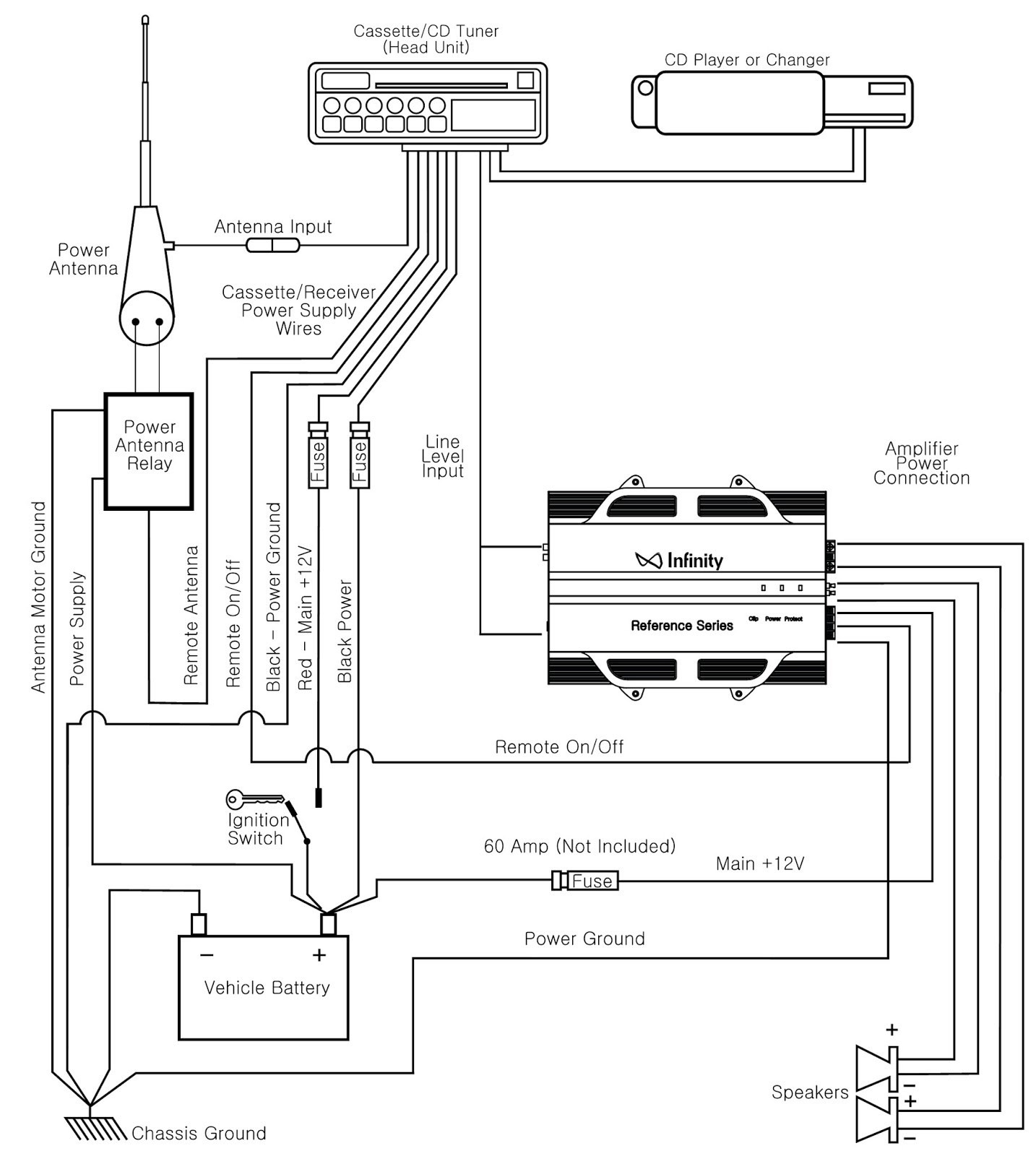
Diagram Bmw System Wiring Diagram Full Version Hd Quality Wiring Diagram Mediagrame Martamenegatti It

Diagram 30 Rv Panel Wiring Diagram Full Version Hd Quality Wiring Diagram Mediagrame Antichemurasorrento It
Diagram Car Inverter Wiring Diagram Full Version Hd Quality Wiring Diagram Solardiagrams Hotelrigelcatania It

Diagram Free Isuzu Wiring Diagram Full Version Hd Quality Wiring Diagram Outletdiagram Hotelrigelcatania It

Diagram 12 24 Rectifier Wiring Diagram Full Version Hd Quality Wiring Diagram Mediagrame Antichemurasorrento It
Diagram Aeg Oven Circuit Diagram Full Version Hd Quality Circuit Diagram Ediagramming Martamenegatti It
Diagram Nv4500 Wiring Diagram Full Version Hd Quality Wiring Diagram Solardiagrams Parcodellegite It

Diagram Dodge Charger Shelby Radio Wiring Diagram Full Version Hd Quality Wiring Diagram Jdiagram Antichemurasorrento It
2 50w 100w Bluetooth 5 0 Dual Tpa3116d2 Power Subwoofer Amplifier Board 2 1 Channel Tpa3116 Audio Amplificador Ecualizador Bluetooth

Diagram Nord Motor Wiring Diagram Full Version Hd Quality Wiring Diagram Ediagramming Martamenegatti It

Diagram 600va Inverter Circuit Diagram Full Version Hd Quality Circuit Diagram Speakerdiagrams Parcodellegite It
Diagram Bazooka Wire Harness Diagram Full Version Hd Quality Harness Diagram Solardiagrams Hotelrigelcatania It

Diagram E 150 Wiring Diagram Full Version Hd Quality Wiring Diagram Hassediagram Parcodellegite It
Diagram Subaru Exiga User Wiring Diagram Full Version Hd Quality Wiring Diagram Mediagrame Antichemurasorrento It

Diagram Key Switch Wiring Diagram Full Version Hd Quality Wiring Diagram Solardiagrams Hotelrigelcatania It
Post a Comment for "100w Spectra To Tone Remote Wiring Diagram"